personal website of ryan r. curtin

At the time of power supply design, it was known that a USB hard drive and a Nokia N810 would need to be powered, using the car's 12V auxiliary power system. The system would need to be able to supply up to 3A to power the hard drive and N810 simultaneously.
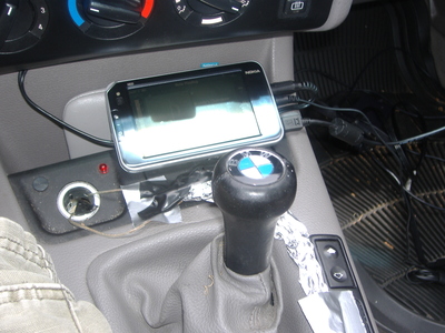
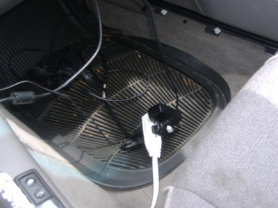
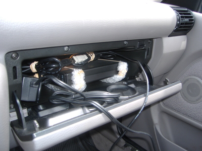
II. Proof-of-concept with AC InverterFirst, the design was tested with a simple AC inverter from Wal-Mart. The inverter was connected to the cigarette lighter indirectly with a wire (otherwise the N810 interface was obstructed), which was then connected to both the N810 charger and USB enclosure's power supply. The enclosure was wrapped mildly in bubble wrap to help reduce vibrations. The inverter and the wires were wrapped in aluminum foil in a hack of attempt to remove ambient electrical noise. Figures 1, 2, 3, and 4 show this setup.
 Figure 1. Frontend and power hookup. |
 Figure 2. Foiled AC inverter abomination. |
 Figure 3. Power distribution causes passenger discomfort. |
 Figure 4. Bleeding-edge vibration damping technology. |
While this power system did work successfully, it had one very prominent problem: the AC inverter and the power adapters for the N810 and the USB drive injected an intolerable amount of noise into the music! This noise was likely caused by unclean oscillators inside of the power supplies. The noise also was caused in part by the alternator.
III. Noise Reduction with Dual Buck Converter DesignUnfortunately, the alternator noise problem could not be solved; however, the noise produced by the AC inverter and the USB hard drive's power supply could be eliminated by using a DC-to-DC converter that would supply both 12V and 5V. The hard drive enclosure (which in the proof-of-concept system shown above an Eagle M enclosure) used was a Thermaltake A2396 [1], which takes both 12V and 5V inputs.
After some searching, the LM2576 [2, 3] was chosen for its high current limits and its simplicity. The LM2576 deals with the switching circuitry itself; all an application has to do is find an inductor, some capacitors, and some wires. This approach keeps the number of potentially failing devices to a minimum, and although the engineer at work on this project is a Georgia Tech electrical engineer with significant knowledge in the field of power, it is certain that National Instruments can make a more durable, effective, failure-resistant device than a bored graduate student; National Instruments engineers turn functional product designs into 6-digit salaries, whereas graduate students lose sleep, miss deadlines, and are rewarded with more work as a partial result of pursuing personal projects.
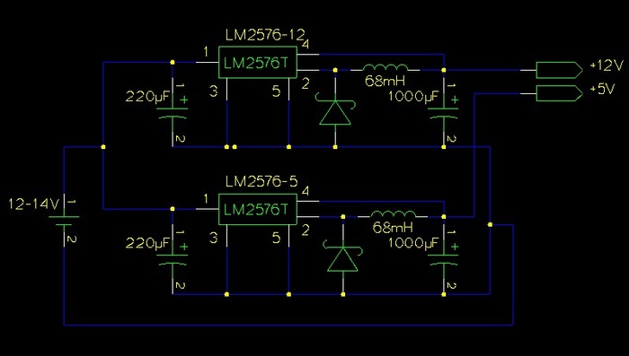
The LM2576 datasheet gives a range of inductor values for both the LM2576-5 and LM2576-12 (on page 12) based on the maximum input voltage and the maximum output current. Since a car battery will sometimes supply up to 14 or 15 volts, and we will expect a maximum of 3A current, the correct inductor value for both the LM2576-5 and LM2576-12 is 68mH. Therefore, two 68mH inductors were purchased, along with one LM2576-5 and one LM2576-12. The power supply circuit diagram can be seen in Figure 6.

After this circuit was designed, it was assembled and soldered onto some surplus board. The bottom was covered with electrical tape (to prevent shorts) and it was epoxied into a nearby box, which had unnecessary venting holes drilled into the top of it. Heat sinks were placed onto the LM2576s, which, after testing the unit, may not actually have been necessary. The power connectors for both the USB hard drive and the N810 charger were removed from their original power supplies and soldered onto the board.
With the power supply completed, it was mounted into the car; awaiting a better mounting location, it was placed into the glovebox and the leads for the battery were attached to the cigarette lighter leads (under the cigarette lighter, unlike in Figure 1).
The power supply was tested during a hot day. The system was left running for several hours on a long car trip and was periodically checked for problems such as overheating or nausea. However, there were absolutely no problems, and even after one year of steady use no parts have needed replacement.
Also, as expected at the outset of this power supply design, the noise in the music was reduced beyond audible detection. However, when the N810 is not actively using the audio output device, it will pick up electrical noise from the alternator and make a similar square-wave sound in the audio. This particular problem was addressed in the next section (by never letting the N810 release the audio output device) [4].
Overall, the design of the dual LM2576 power supply was simple, effective, and cheap; it has exhibited no deficiencies or problems to date.
V. References